Gazebo Chassis
danger
Installing from a package may not work. This article is not yet complete.
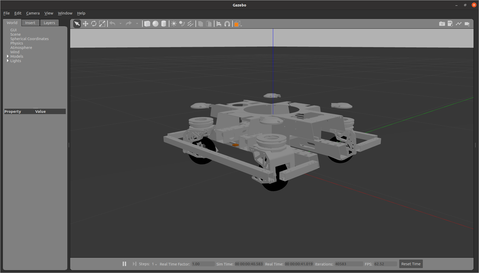
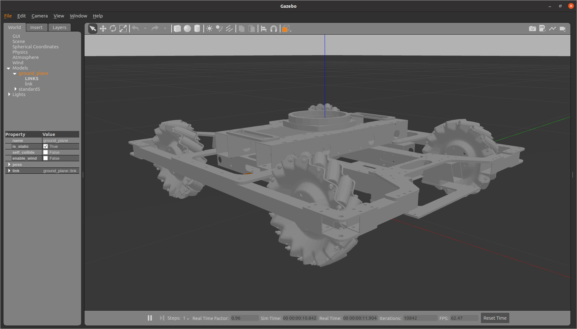
This article will take you through the manipulation of the mecanum wheels robot and the swerve drive robot chassis in the Gazebo simulation.
Running the simulation
Installing from the package
sudo apt install ros-noetic-rm-rm_gazebo ros-noetic-rm-description
Compile from source
Go to your workspace (assuming it is named rm_ws), pull this rm_control in your workspace and install the package dependencies using rosdep and compile.
cd ~/ws_ws/src
git clone https://github.com/rm-controls/rm_control.git
rosdep install --from-paths . --ignore-src
catkin build
tip
You must make sure that your rosdep installation and initialization is correct.
caution
You should perform the following actions in your daily development computer; and not install simulation and visualization-related packages on top of the computing device on the robot, let alone run simulations on it.
Set the environment variable ROBOT_TYPE to the target robot :
- Rudder Wheel
- McNamee Wheel


Start the simulation of the target robot
mon launch rm_gazebo empty_world.launch
The target robot simulation is started while the robot's gimbal and launch mechanism are disabled (loading the launch mechanism when the gimbal mechanism is not loaded will generate an error), because our goal is to control the motion of the chassis in the simulation.
Run the controller
Install from package
- rudder-wheel
- McNamee wheel
Controlling the chassis with the command line
Go to your workspace (assuming it is named rm_ws), pull the simulation package rm_chassis_controllers that you will use for this tutorial in your workspace, and install the package dependencies using rosdep.
cd ~/ws_ws/src
git clone https://github.com/rm-controls/rm_controllers.git
rosdep install --from-paths . --ignore-src
catkin build
Load and start the chassis controller.
mon launch rm_chassis_controllers load_controllers.launch
Set the serial number of mode to set the chassis mode where:
0 represents RAW mode, it is the initial state of the chassis, it is the initial state of the chassis, the chassis cannot move in this mode.
1 represents FOLLOW mode, is the gimbal follow mode, the chassis follow the direction of the gimbal movement.
2 represents GYRO mode, is the small gyro mode, the chassis rotates with itself as the center.
3 represents TWIST mode, it is twist mode, the rotation of the chassis will not be affected by the direction of the gimbal.
Set accel(acceleration), set the linear and angular acceleration of the chassis and set the limit power of the chassis in power_limit.
rostopic pub /controllers/chassis_controller/command rm_msgs/ChassisCmd "mode: 0
accel:
  linear: {x: 0.0, y: 0.0, z: 0.0}
  angular: {x: 0.0, y: 0.0, z: 0.0}
power_limit: 0.0
follow_source_frame: ''
stamp: {secs: 0, nsecs: 0}"
``''

The command to set the speed of the chassis to move is as follows.

```shell
rostopic pub /cmd_vel geometry_msgs/Twist "linear:
  x: 0.0
  y: 0.0
  z: 0.0
angular:
  x: 0.0
  y: 0.0
  z: 0.0"