rm-controls 101
danger
Installing from a package may not work. This article is not yet complete.
This article will take you through building a simple single-joint URDF and loading it into Gazebo, and then loading two simple PID controllers to control its position and speed, respectively. Environment and dependencies.
- Ubuntu
- ROS
- catkin tools
- rosmon
There is a detailed official installation tutorial for all of the above environments and dependencies, so I won't go into it here.
info
Our daily development is usually done on Ubuntu 20.04 (ros-noetic), and usually the CI also makes sure that the program is running correctly on Ubuntu 18.04 (ros-melodic). Bugs may occur on older versions of Mythic2 than Ubuntu 16.04 (ros-kinetic), feel free to report them to rm_control Issue Tracker and rm_ controlles Issue Tracker.
caution
It is strongly recommended to use catkin tools instead of catkin_make Use mon instead of roslaunch, and use the catkin_tools and rosmon commands for the rest of the tutorial.
Create the package where the tutorial files will be placed
Go to your workspace (assuming it is named rm_ws) and create the package in your workspace that will hold the tutorials rm_controls_tutorials
cd ~/rm_ws/src
catkin create pkg rm_controls_tutorials
catkin build
cd rm_controls_tutorials
mkdir urdf launch config
Run simulation
If you are only running a simple simulation of a single 3508 driven joint, you don't need the code for rm-controls, so you can say that this section is actually an introduction to ros-controls + gazebo.
caution
You should do the following on your daily development computer; and not install simulation and visualization-related packages on the computing device on the robot, let alone run the simulation on it. We recommend installing Ubuntu server for the robot and accessing it via ssh.
Install the dependencies:
sudo apt install ros-noetic-xacro ros-noetic-gazebo-ros-control
Create URDF and run the simulation
Create the file urdf/rmrobot.urdf.xacro in your favorite text editor as follows.
<?xml version="1.0"? >
<robot xmlns:xacro="http://www.ros.org/wiki/xacro" name="rmrobot">
    <! -- Constants for robot dimensions -->
    <xacro:property name="mass" value="0.5"/> <! -- arbitrary value for mass -->
    <xacro:property name="width" value="0.1"/> <! -- Square dimensions (widthxwidth) of beams -->
    <xacro:property name="height1" value="1"/> <! -- Link 1 -->
    <xacro:property name="height2" value="0.5"/> <! -- Link 2 -->
    <xacro:property name="axel_offset" value="0.05"/> <! -- Space btw top of beam and the each joint -->
    <! -- Used for fixing robot to Gazebo 'base_link' -->
    <link name="world"/>
    <joint name="fixed" type="fixed">
        <parent link="world"/>
        <child link="link1"/>
    </joint>

    <link name="link1">
        <collision
            <origin xyz="0 0 ${height1/2}" rpy="0 0 0"/>
            <geometry
                <box size="${width} ${width} ${height1}"/>
            </geometry>
        </collision>
        <visual
            <origin xyz="0 0 ${height1/2}" rpy="0 0 0"/>
            <geometry
                <box size="${width} ${width} ${height1}"/>
            </geometry>
            <material name="orange"/>
        </visual>
        <inertial
            <origin xyz="0 0 ${height1/2}" rpy="0 0 0"/>
            <mass value="${mass}"/>
            <inertia
                    ixx="${mass / 12.0 * (width*width + height1*height1)}" ixy="0.0" ixz="0.0"
                    iyy="${mass / 12.0 * (height1*height1 + width*width)}" iyz="0.0"
                    izz="${mass / 12.0 * (width*width + width*width)}"/>
        </inertial>
    </link>
    <joint name="joint1" type="revolute">
        <axis xyz="0 1 0"/>
        <origin xyz="0 ${width} ${height1 - axel_offset}" rpy="0 1.57 0"/>
        <! -- limit not work while type="continuous"-->
        <limit effort="5." velocity="50." lower="-1e9" upper="1e9"/>
        <dynamics damping="0.01" friction="0.02"/>
        <parent link="link1"/>
        <child link="link2"/>
    </joint

    <link name="link2">
        <collision
            <origin xyz="0 0 ${height2/2 - axel_offset}" rpy="0 0 0"/>
            <geometry
                <box size="${width} ${width} ${height2}"/>
            </geometry>
        </collision>
        <visual
            <origin xyz="0 0 ${height2/2 - axel_offset}" rpy="0 0 0"/>
            <geometry
                <box size="${width} ${width} ${height2}"/>
            </geometry>
            <material name="black"/>
        </visual>
        <inertial
            <origin xyz="0 0 ${height2/2 - axel_offset}" rpy="0 0 0"/>
            <mass value="${mass}"/>
            <inertia
                    ixx="${mass / 12.0 * (width*width + height2*height2)}" ixy="0.0" ixz="0.0"
                    iyy="${mass / 12.0 * (height2*height2 + width*width)}" iyz="0.0"
                    izz="${mass / 12.0 * (width*width + width*width)}"/>
        </inertial>
    </link>

    <transmission name="tran1">
        <type>transmission_interface/SimpleTransmission</type>
        <joint name="joint1">
            <hardwareInterface>hardware_interface/EffortJointInterface</hardwareInterface>
        </joint>
        <actuator name="joint1_motor">
            <hardwareInterface>hardware_interface/EffortJointInterface</hardwareInterface>
            <mechanicalReduction>19.2032</mechanicalReduction>
        </actuator>
    </transmission>
    <gazebo>
        <plugin name="gazebo_ros_control" filename="libgazebo_ros_control.so">
            <robotNamespace>/</robotNamespace>
        </plugin>
    </gazebo>
</robot>
The above code creates a simple duplex with link1 fixed and link2 connected with joint1, each link has its properties of collision, appearance and inertia.
Create the launch file launch/load_gazebo.launch with your favorite editor as follows:
<launch>
    <! -- We resume the logic in empty_world.launch, changing only the name of the world to be launched -->
    <include file="$(find gazebo_ros)/launch/empty_world.launch"/>
    <! -- push robot_description to factory and spawn robot in gazebo -->
    <param name="robot_description"
           command="$(find xacro)/xacro $(find rm_controls_tutorials)/urdf/rmrobot.urdf.xacro"/>
    <node name="spawn_urdf" pkg="gazebo_ros" type="spawn_model" clear_params="true"
          args="-param robot_description -urdf -model rmrobot" output="screen"/>
</launch>
The above launch file starts Gazebo, loads the URDF into the parameter server, and then informs Gazebo to load the URDF into the simulation world. Run the launch file
mon launch rm_controls_tutorials load_gazebo.launch
The simulation will start and you can see the two links, when a certain force is applied to link2, link2 will oscillate and slowly stop.
Now you can try to control joint1 in the simulation : [run controller](#run controller)
Run the physical
Preparing the CAN device
Install the SocketCAN command line debugging tool on Linux.
sudo apt install can-utils
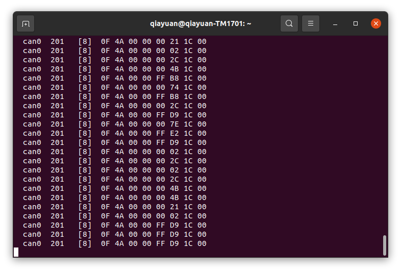
Set the CAN ID of the 3508 to 0x201 and connect it to can0 (note the high and low wire sequences), if you are testing on an Intel NUC or your laptop, you can use rm_usb2can to get the CAN interface. Run the following code.
    sudo ip link set can0 up type can bitrate 1000000
    candump can0
You can see the received CAN frame of 3508:
Configuring and running rm_hw
First you need to install rm_hw and its dependencies, you can choose to install from package or compile from source:
Install from package
sudo apt install ros-noetic-rm-hw
Compile from source
First clone the rm-controls repository in your PC: ```shell
git clone git@github.com:rm-controls/rm_control.git #SSH
#git clone https://github.com/rm-controls/rm_control.git
If you want to deploy to a robot or use a computing device on a robot for testing
caution
You should not clone the repository directly to the robot computing device, and you should not pass the entire rm-controls metapackage to the robot. Because rm-controls contains emulation, it is necessary to install many emulation and graphics dependencies that the robot does not need.
Install the dependencies using rosdep and compile.
rosdep install --from-paths . --ignore-src
catkin build
tip
Make sure your rosdep is properly installed and initialized.
Create the underlying configuration file config/rm_hw.yaml with your favorite editor as follows.
``yaml bus:
- can0 loop_frequency: 1000 cycle_time_error_threshold: 0.001
actuators: joint1_motor: bus: can0 id: 0x201 type: rm_3508 lp_cutoff_frequency: 60
Create the launch file ``launch/load_rm_hw.yaml`` with your favorite editor as follows

```xml
<launch>
    <! -- push robot_description to factory and spawn robot in gazebo -->
    <param name="robot_description"
           command="$(find xacro)/xacro $(find rm_controls_tutorials)/urdf/rmrobot.urdf.xacro"/>
    <rosparam file="$(find rm_hw)/config/actuator_coefficient.yaml" command="load" ns="rm_hw"/>
    <rosparam file="$(find rm_controls_tutorials)/config/rm_hw.yaml" command="load" ns="rm_hw"/>
    <node name="rm_hw" pkg="rm_hw" type="rm_hw" respawn="false" clear_params="true"/>
    <node name="robot_state_publisher" pkg="robot_state_publisher" type="robot_state_publisher"/>
</launch>
Run rm_hw:
mon launch rm_controls_tutorials load_rm_hw.launch
If there is an error.
[main]: Set scheduler failed, RUN THIS NODE AS SUPER USER.
Then you need to set sudo password free. If you encounter a warning like.
[RmRobotHWLoop::update]: Cycle time exceeded error threshold by: 0.0017126s, cycle time: 0.003712596s, threshold: 0.001s
For real-time issues, you need to replace the real-time kernel. For Intel NUC we recommend using linux-xanmod-rt kernel, for Jetson series or Manifo 2G, you can refer to compiling real-time kernel for more information. steps.
Running the controller
Create the controller configuration file config/controllers.yaml with your favorite editor as follows.
controllers:
  joint_state_controller:
    type: joint_state_controller/JointStateController
    publish_rate: 50
  joint1_position_controller:
    type: effort_controllers/JointPositionController
    joint: joint1
    pid:
      {
        p: 30,
        i: 0.0,
        d: 0.8,
        i_clamp_max: 1,
        i_clamp_min: -1,
        antiwindup: true,
      }
  joint1_velocity_controller:
    type: effort_controllers/JointVelocityController
    joint: joint1
    pid: { p: 0.8, i: 0, d: 0.0, i_max: 0.0, i_min: 0.0, antiwindup: true }
where joint_state_controller is the joint state publisher and the remaining two controllers are for joint position and velocity control with PIDs respectively.
Use your favorite editor to create launch file urdf/load_controller.launch as follows.
<launch>
    <rosparam file="$(find rm_controls_tutorials)/config/controllers.yaml" command="load"/>
    <! -- load the controllers -->
    <node name="controller_loader" pkg="controller_manager" type="controller_manager"
          respawn="false" output="screen"
          args="load
          controllers/joint_state_controller
          controllers/joint1_position_controller
          controllers/joint1_velocity_controller
"/>
</launch>
When Gazebo or rm_hw is running, the controllers are loaded with the following command
mon launch rm_controls_tutorials load_controllers.launch
State fetching
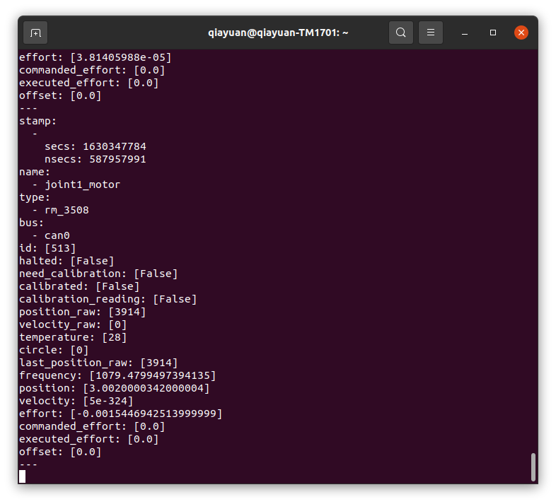
Use rostopic to get the state of the actuator (3508 motor) and rotate the rotor of the 3508 to observe the data.
rostopic echo /actuator_states
Use the following command to turn on joint_state_controller, which will post the joint states.
rosservice call /controller_manager/switch_controller "start_controllers: ['controllers/joint_state_controller']
stop_controllers: ['']
strictness: 1
start_asap: true
timeout: 0.0"
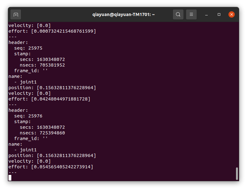
Use rostopic to get the state of joint1 and rotate the output axis of 3508 to see the data.
rostopic echo /joint_states
danger
Next the joints/actuators will move, if you are trying to use the real 3508 motors, please stabilize the motors to prevent accidental injuries.
Position controller
Stop running the speed controller and run the command for the position controller as follows.
rosservice call /controller_manager/switch_controller "start_controllers: ['controllers/joint1_position_controller']
stop_controllers: ['controllers/joint1_velocity_controller']
strictness: 1
start_asap: true
timeout: 0.0"
At this point, the closed-loop position is already in progress, and by sending the position command 0.0 through the rostopic, you can observe that the link2 moves rapidly to the horizontal position in the simulation or the real motor moves to the zero point. Change the value of the command sent to observe the phenomenon. At this point it is easy to visualize the individual data
rostopic pub /controllers/joint1_position_controller/command std_msgs/Float64 "data: 0.0"
tip
In ROS, all data is in international standard units, e.g., rad for angle and rad/s for angular velocity.
Speed controller
The command to stop running the position controller and run the speed controller is as follows.
rosservice call /controller_manager/switch_controller "start_controllers: ['controllers/joint1_velocity_controller']
stop_controllers: ['controllers/joint1_position_controller']
strictness: 1
start_asap: true
timeout: 0.0"
By sending the position command 3.1415 from rostopic, you can observe the link2 in the simulation or the real motor rotating at half a revolution per second.
rostopic pub /controllers/joint1_velocity_controller/command std_msgs/Float64 "data: 3.1415"
TODO Visualization
ROS provides a lot of visualization tools, you can plot the image of each data of the motor, view the relationship of each coordinate system, and dynamically adjust the PID parameters.