intro
Why rm-controls?
Very high code reuse rate
We designed the code architecture with a strong focus on code reuse, modularizing and parameterizing the code so that different robots only need to load different numbers and types of controllers based on the configuration file. For example, after developing the base module for the infantry, when developing the dual gimbal sentry, you only need to write the configuration .yaml file and do not need to write or modify any line of code except for the development of the decision level. The following figure shows the deployment of a robot that uses this code.
The following code is the partial configuration file for the sentry's gimbal controller. You can see that the configuration files for the top and bottom gimbal have the same structure, and that the two gimbal controllers are loaded independently and dynamically, and then get the parameters for each of the two controllers, including the names of the joints it will control, and the names of the external interfaces (in the form of ros topics, etc.).
upper_gimbal_controller:
  type: rm_gimbal_controllers/Controller
  detection_topic: "/upper_detection"
  camera_topic: "/upper_camera/camera_info"
  yaw:
    joint: "upper_yaw_joint"
    pid:
      {
        p: 5.0,
        i: 0,
        d: 0.3,
        i_clamp_max: 0.0,
        i_clamp_min: -0.0,
        antiwindup: true,
      }
  pitch:
    joint: "upper_pitch_joint"
    pid:
      {
        p: 8.0,
        i: 50,
        d: 0.3,
        i_clamp_max: 0.1,
        i_clamp_min: -0.1,
        antiwindup: true,
      }
lower_gimbal_controller:
  type: rm_gimbal_controllers/Controller
  detection_topic: "/lower_detection"
  camera_topic: "/lower_camera/camera_info"
  yaw:
    joint: "lower_yaw_joint"
    pid:
      {
        p: 5.0,
        i: 0,
        d: 0.3,
        i_clamp_max: 0.0,
        i_clamp_min: -0.0,
        antiwindup: true,
      }
  pitch:
    joint: "lower_pitch_joint"
    pid:
      {
        p: 5.0,
        i: 100,
        d: 0.2,
        i_clamp_max: 0.4,
        i_clamp_min: -0.4,
        antiwindup: true,
      }
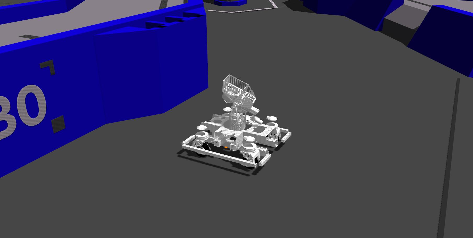
Multi-rigid body dynamics simulation
All robots can be simulated in Gazebo with multi-rigid body dynamics, and there is no need to port the code between simulation and real robot run, it is the same code or even the same binary file. Except for the launch controller, other modules and controllers are debugged and tested in the simulation during development, and time can be paused when the breakpoint is interrupted. For example, the swerve drive robot spent less than a day to test and debug all the programs after the machining and assembly. The following figure shows the simulation of the swerve drive robot in the RMUC field.
Continuous Integration
We used industrial_ci on our self-built gitlab server for continuous integration of the code, which automatically compiles, tests and publishes the code to the apt source.
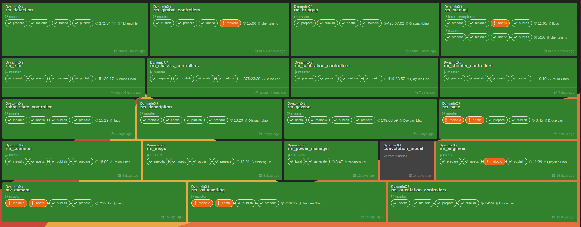
Once development is stable on a particular robot, other robots can use the installation or upgrade to get the latest features of the software. For example, use the two-line command to complete the installation or update of the chassis controller.
sudo apt update
sudo apt install ros-noetic-rm-chassis-controllers
info
Since it's open-sourced on GitHub, we've moved most of our repositories to GitHub hosting and are running CLs using GitHub Actions.
Good compatibility
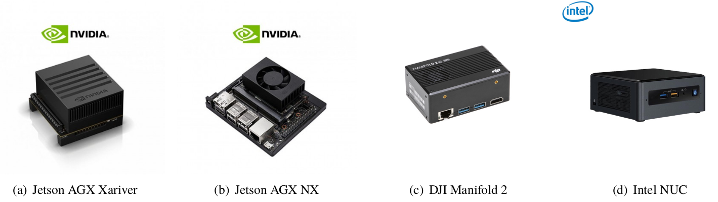
The hardware interface uses Linux's SocketCAN and sysfs, meaning it can run on ARM devices with a CAN bus like the Jetson AGX and Manifo 2G, and We also made a usb to CAN device: rm_usb2can, which supports running on any x86 platform, e.g. Intel NUC and team members' laptops, in RMUC we focus on Intel NUC, also was officially deployed for use on Manifo 2G Computing 2 in the 2021 summer camp for high school students. The following figure shows some of the compatible computing devices.
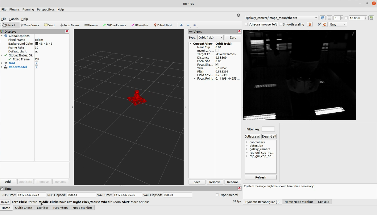
Rich debugging tools
With the ROS ecosystem, you can use a variety of visual debugging tools to remotely view motor data, calculation results, and images. Dynamic_reconfigure can also be used for dynamic tuning. shows the debugging interface we built, supported by rqt, so we can build our own debugging GUI without writing code.