Software framework
rm-controls
tip
If you are not familiar with ros-controls, please read prerequisite first.
The rm-controls program consists of several ROS packages, including the metapackage: rm_control which provides a common interface to the underlying hardware and simulation, the metapackage rm_controllers which is the controller for each common module, and the package rm_manual which is responsible for general robot operations and the sentry decision package rm_fsm.
- rm_control
- rm_msgs: Customized ROS topic messages, services, actions
- rm_common: common functions, algorithms, referee system send/receive, ui
- rm_description: URDF for all robots, defines: relations between robot coordinate systems, mapping of motors and joints, joint limits, physical properties needed for simulation
- rm_hw: Node of the same name communicates with the actuator through SocketCAN to get data and send commands, providing hardware interface to the controller when the real robot is running
- rm_gazebo: The same name Gazebo Plugin provides hardware interface to the controller during simulation runtime
- rm_dbus: dbus remote control driver receiver node
- rm_controllers
- robot_state_controller: high performance version of robot_state_publisher, high frequency maintenance tf
- rm_chassis_controllers: chassis controllers for mecanum wheels robot, swerve drive robot, and balancing chassis robot
- rm_gimbal_controllers: head controllers with shooting model and tracking filter prediction
- rm_shooter_controllers: controllers that operate friction wheels and trigger to shoot
- rm_calibration_controllers: controllers for calibrating actuator positions
- rm_manual: general robot decision making
- rm_fsm: sentry robot decision Not open source.
- rm_detection: visual recognition of armor plates and windmills
- rm_stone: ore and obstacle block visual recognition
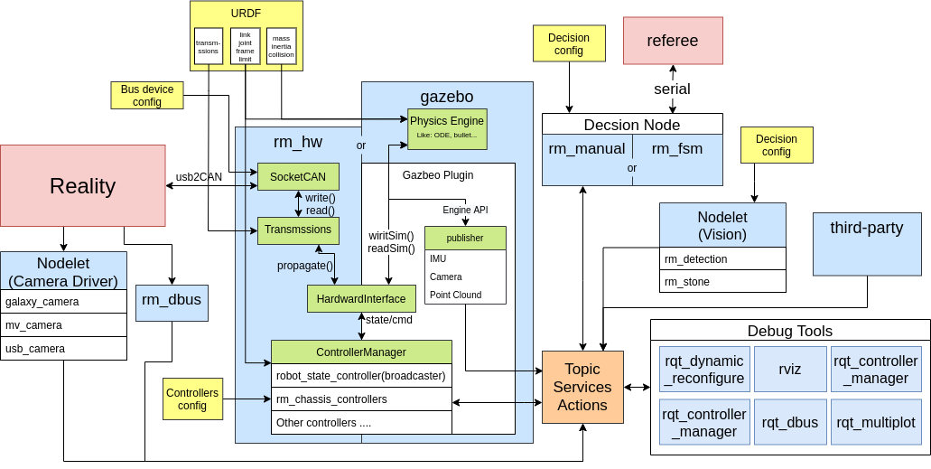
As shown above, the controller gets the handle of each sensor and actuator from the HardwareInterface to update data and send commands, while receiving commands from other nodes and publishing its own state through ROS topics, services and actions. The camera driver and vision algorithm run in the same node through nodelet and achieve "zero copy". The decision layer reads the referee system data through the serial port, and performs topic, service, and action based on the referee system data and operator commands for the above nodes and third-party nodes (e.g., move_base path planning, [moveit](https://moveit.ros. org/) trajectory planning). The configuration files and data are loaded by rosparam to the ROS parameter server and are available to each node by query. Multiple debugging tools also interact through ROS topics, services, and actions.
Prerequisite
The following describes the mechanisms involved in ros-control in the physical and Gazebo simulations.
ros-control with real hardware
In the figure below, ros-control provides a mechanism whereby sensor data such as encoders of actuators are read and mapped to robot states such as joints via TransmissionsInterface. Joint) and other robot states, and provide these state interfaces to the controller; after the controller calculates and obtains the joint commands with restrictions, then maps them to motor commands and sends them to the motor. The controller manager can load, start and stop various controllers in real time (compiled as a dynamic library).
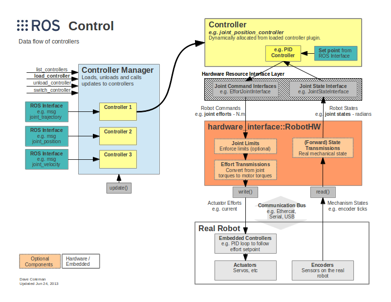
Hardware Interfaces
Common hardware interfaces provided to controllers
- Joint Command Interface - Interface for sending joint commands
- Effort Joint Interface - Used to send commands to joints corresponding to actuators whose command is torque/force (e.g. RoboMaster 3508)
- Velocity Joint Interface - Used to send commands to joints corresponding to velocity actuators (e.g., partial servos)
- Position Joint Interface - used to send commands to joints corresponding to position actuators (e.g. most servos)
- Joint State Interfaces - Joint state acquisition interfaces to obtain the position, velocity and force (force or torque) of the joint
- Actuator State Interfaces - Actuator state acquisition interface to obtain the position, velocity and force (force or torque) of the actuator
- Actuator Command Interfaces - Actuator command sending interface, similar to the joint command interface
- Force-torque sensor Interface - Force-torque sensor interface
- IMU Sensor Interface - IMU sensor interface
Transmissions
Transmissions are the state and command mapping of the actual robot actuators to the joints, and are available as simple reduction ratios (changing the positive or negative can reverse the motor), differential transmissions (common for two joints at the end of the robot arm), and dual actuators (two motors driving one joint). The following diagram shows a sketch of differential Transmissions and how they are calculated.
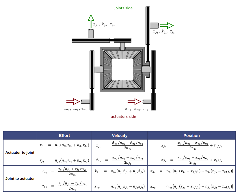
The following code is for the gimbal pitch axis actuator in the infantry robot URDF: pitch_joint_motor and simple_transmission for the gimbal pitch joint pitch_joint transmission_interface/html/c++/classtransmission__interface_1_1SimpleTransmission.html), because the pitch axis is 6020 motor direct drive, the reduction ratio is 1.0, and the actual motor steering is the opposite of the joint defined steering With this mapping, the head controller only uses the joint state without considering the different robot motor mounting positions, directions and initial values.
<transmission name="trans_pitch_joint">
    <type>transmission_interface/SimpleTransmission</type
    <actuator name="pitch_joint_motor">
        <mechanicalReduction>-1</mechanicalReduction
    </actuator
    <joint name="pitch_joint">
        <offset>1.559</offset
        <hardwareInterface>hardware_interface/EffortJointInterface</hardwareInterface
    </joint
</transmission>
ros-control and Gazebo
Thanks to the above mechanism, the controller can be loaded onto the hardware interface or into the Gazebo emulator, as shown in the figure below. It is worth mentioning that both the real hardware and the emulated controller are the same code, there is no porting or recompiling process, and even the same binary is used (compiled and tested by the server CI and published to apt sources and installed).
