hardware_specifications
Hardware Specifications
CAN bus
Built-in CAN
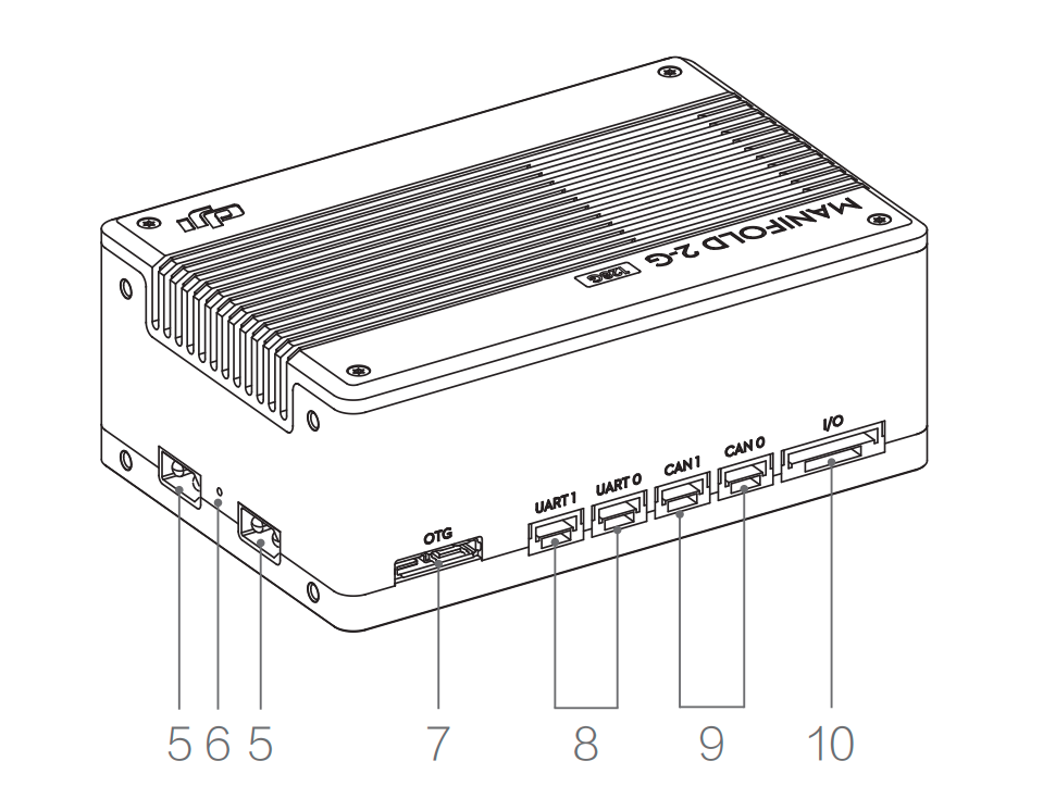
Both the Jetson AGX Xavier/NX/TX2 and the Manifo 2G-G (TX2) have two build-in CAN bus interfaces. The diagram below 9 shows the physical interface locations for the built-in CAN of the Jetson 2.
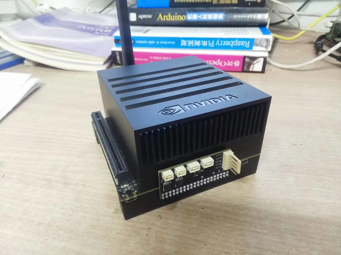
The following image shows the homebrew Jetson AGX Xavier wiring board.
All of the above can be easily used with the CAN interface via the SocketCAN mechanism provided by the Linux mainline.
USB to CAN
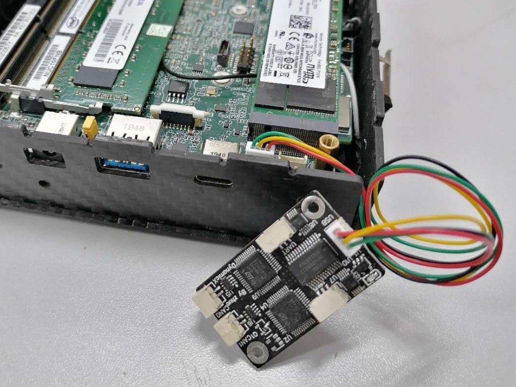
We have also developed the USB to CAN module for Intel NUC and the team's debug PC. The driver for this module is included in the Linux mainline and can be plugged in to access CAN via SocketCAN.
The following picture shows: Stable connection of the USB to CAN module using the NUC USB 1.25mm terminal on the motherboard.
Other interfaces
GPIO, PWM, I2C interfaces are under development, see road map for details.
Module topology
The following diagram shows the basic hardware topology block diagram of the entire robot (the engineering robot topology varies widely throughout the robot and is not given here).
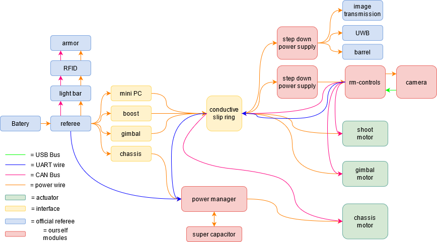
The basic hardware topology of the robot is composed of two major parts, the gimbal and the chassis, which are separated by a conductive slip ring as a dividing line. The 12V, 19V, 5V and 3.3V voltage sets on the car are provided by LM25116, LM3150, SY8303 and RT9193 respectively.