rm-controls 101
danger
从包安装可能无法使用。本文还未完成。
本文将带你建立一个简单的单关节 URDF 并加载到 Gazebo 中,然后先后加载两个简单的 PID 控制器分别对它进行位置和速度控制。 环境与依赖:
- Ubuntu
- ROS
- catkin tools
- rosmon
上述环境和依赖均有详细的官方安装教程,在此不过多赘述。
info
我们的日常开发一般在 Ubuntu 20.04(ros-noetic)上进行,而通常 CI 还会确保程序在 Ubuntu 18.04 (ros-melodic)上运行是正确的。在妙算 2 的版本过老旧 Ubuntu 16.04 (ros-kinetic)上有可能会出现 bug,欢迎报告 rm_control Issue Tracker 和 rm_controlles Issue Tracker.
caution
强烈建议使用 catkin tools 代替 catkin_make 使用 mon 代替 roslaunch ,后面的教程均使用 catkin_tools 和 rosmon 的指令。
创建放置教程文件的包
进入你的工作空间(假设名为 rm_ws),在你的工作空间中创建存放本次教程需要用的包 rm_controls_tutorials
cd ~/rm_ws/src
catkin create pkg rm_controls_tutorials
catkin build
cd rm_controls_tutorials
mkdir urdf launch config
运行仿真
如果只进行简单的单个 3508 驱动的关节仿真,并不需要 rm-controls 的相关代码,可以说本节其实是 ros-control + gazebo 的入门。
caution
你应该在你的日常开发电脑中执行下述操作;而不在机器人上的计算设备上面安装仿真以及可视化相关的包,更不要在上面运行仿真。我们推荐为机器人安装 Ubuntu server ,通过 ssh 来访问机器人。
安装依赖:
sudo apt install ros-noetic-xacro ros-noetic-gazebo-ros-control
创建 URDF 并运行仿真
用你最喜欢的文本编辑器创建文件 urdf/rmrobot.urdf.xacro 如下:
<?xml version="1.0"?>
<robot xmlns:xacro="http://www.ros.org/wiki/xacro" name="rmrobot">
    <!-- Constants for robot dimensions -->
    <xacro:property name="mass" value="0.5"/> <!-- arbitrary value for mass -->
    <xacro:property name="width" value="0.1"/> <!-- Square dimensions (widthxwidth) of beams -->
    <xacro:property name="height1" value="1"/> <!-- Link 1 -->
    <xacro:property name="height2" value="0.5"/> <!-- Link 2 -->
    <xacro:property name="axel_offset" value="0.05"/> <!-- Space btw top of beam and the each joint -->
    <!-- Used for fixing robot to Gazebo 'base_link' -->
    <link name="world"/>
    <joint name="fixed" type="fixed">
        <parent link="world"/>
        <child link="link1"/>
    </joint>

    <link name="link1">
        <collision>
            <origin xyz="0 0 ${height1/2}" rpy="0 0 0"/>
            <geometry>
                <box size="${width} ${width} ${height1}"/>
            </geometry>
        </collision>
        <visual>
            <origin xyz="0 0 ${height1/2}" rpy="0 0 0"/>
            <geometry>
                <box size="${width} ${width} ${height1}"/>
            </geometry>
            <material name="orange"/>
        </visual>
        <inertial>
            <origin xyz="0 0 ${height1/2}" rpy="0 0 0"/>
            <mass value="${mass}"/>
            <inertia
                    ixx="${mass / 12.0 * (width*width + height1*height1)}" ixy="0.0" ixz="0.0"
                    iyy="${mass / 12.0 * (height1*height1 + width*width)}" iyz="0.0"
                    izz="${mass / 12.0 * (width*width + width*width)}"/>
        </inertial>
    </link>
    <joint name="joint1" type="revolute">
        <axis xyz="0 1 0"/>
        <origin xyz="0 ${width} ${height1 - axel_offset}" rpy="0 1.57 0"/>
        <!--      limit not work while type="continuous"-->
        <limit effort="5." velocity="50." lower="-1e9" upper="1e9"/>
        <dynamics damping="0.01" friction="0.02"/>
        <parent link="link1"/>
        <child link="link2"/>
    </joint>

    <link name="link2">
        <collision>
            <origin xyz="0 0 ${height2/2 - axel_offset}" rpy="0 0 0"/>
            <geometry>
                <box size="${width} ${width} ${height2}"/>
            </geometry>
        </collision>
        <visual>
            <origin xyz="0 0 ${height2/2 - axel_offset}" rpy="0 0 0"/>
            <geometry>
                <box size="${width} ${width} ${height2}"/>
            </geometry>
            <material name="black"/>
        </visual>
        <inertial>
            <origin xyz="0 0 ${height2/2 - axel_offset}" rpy="0 0 0"/>
            <mass value="${mass}"/>
            <inertia
                    ixx="${mass / 12.0 * (width*width + height2*height2)}" ixy="0.0" ixz="0.0"
                    iyy="${mass / 12.0 * (height2*height2 + width*width)}" iyz="0.0"
                    izz="${mass / 12.0 * (width*width + width*width)}"/>
        </inertial>
    </link>

    <transmission name="tran1">
        <type>transmission_interface/SimpleTransmission</type>
        <joint name="joint1">
            <hardwareInterface>hardware_interface/EffortJointInterface</hardwareInterface>
        </joint>
        <actuator name="joint1_motor">
            <hardwareInterface>hardware_interface/EffortJointInterface</hardwareInterface>
            <mechanicalReduction>19.2032</mechanicalReduction>
        </actuator>
    </transmission>
    <gazebo>
        <plugin name="gazebo_ros_control" filename="libgazebo_ros_control.so">
            <robotNamespace>/</robotNamespace>
        </plugin>
    </gazebo>
</robot>
上述代码创建了一个简单二连杆,并将 link1 固定不动,用 joint1 连接 link2,每个 link 都有它的碰撞、外观、惯量的属性。
用你最喜欢的编辑器 创建 launch 文件 launch/load_gazebo.launch 如下:
<launch>
    <!-- We resume the logic in empty_world.launch, changing only the name of the world to be launched -->
    <include file="$(find gazebo_ros)/launch/empty_world.launch"/>
    <!-- push robot_description to factory and spawn robot in gazebo -->
    <param name="robot_description"
           command="$(find xacro)/xacro $(find rm_controls_tutorials)/urdf/rmrobot.urdf.xacro"/>
    <node name="spawn_urdf" pkg="gazebo_ros" type="spawn_model" clear_params="true"
          args="-param robot_description -urdf -model rmrobot" output="screen"/>
</launch>
上述 launch 文件启动 Gazebo, 将 URDF 载入参数服务器,后通知 Gazebo 将 URDF 载入仿真世界中。运行 launch 文件
mon launch rm_controls_tutorials load_gazebo.launch
就可以开始仿真,可以看到两个连杆,这时候给一定的力作用在 link2 上,link2 将会摆动并慢慢停下。
现在你可以尝试控制仿真中的 joint1 : 运行控制器
运行实物
准备 CAN 设备
安装在 Linux 上 SocketCAN 命令行调试工具:
sudo apt install can-utils
将 3508 的 CAN ID 设为 0x201,并将它连接到 can0(注意高低两根线序),如果你在 Intel NUC 或者你的的笔记本上面测试,可以使用 rm_usb2can 来获得 CAN 接口。运行下列代码:
    sudo ip link set can0 up type can bitrate 1000000
    candump can0
可以看到接收的 3508 的 CAN 帧:
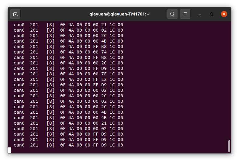
配置并运行 rm_hw
首先需要先安装 rm_hw 及其依赖,你可以选择从包安装或者从源码编译:
从包安装
请先添加源
sudo apt install ros-noetic-rm-hw
从源码编译
首先在个人电脑中克隆 rm-controls 仓库:
git clone git@github.com:rm-controls/rm_control.git #SSH
#git clone https://github.com/rm-controls/rm_control.git
如果你要部署到机器人上或使用机器人上的计算设备进行测试
caution
你不应该把仓库直接克隆到机器人计算设备,也不应该将整个 rm-controls 元包传到机器人上。因为 rm-controls 包含了仿真,需要安装许多机器人不需要的仿真和图形依赖。
使用 rosdep 安装依赖,并编译:
rosdep install --from-paths . --ignore-src
catkin build
tip
确保你的 rosdep 被正确安装和初始化。
用你最喜欢的编辑器创建底层配置文件 config/rm_hw.yaml 如下:
bus:
  - can0
loop_frequency: 1000
cycle_time_error_threshold: 0.001
thread_priority: 95

actuators:
  joint1_motor:
    bus: can0
    id: 0x201
    type: rm_3508
    lp_cutoff_frequency: 60
用你最喜欢的编辑器创建 launch 文件 launch/load_rm_hw.launch 如下:
<launch>
    <!-- push robot_description to factory and spawn robot in gazebo -->
    <param name="robot_description"
           command="$(find xacro)/xacro $(find rm_controls_tutorials)/urdf/rmrobot.urdf.xacro"/>
    <rosparam file="$(find rm_hw)/config/actuator_coefficient.yaml" command="load" ns="rm_hw"/>
    <rosparam file="$(find rm_controls_tutorials)/config/rm_hw.yaml" command="load" ns="rm_hw"/>
    <node name="rm_hw" pkg="rm_hw" type="rm_hw" respawn="false" clear_params="true"/>
    <node name="robot_state_publisher" pkg="robot_state_publisher" type="robot_state_publisher"/>
</launch>
运行 rm_hw:
mon launch rm_controls_tutorials load_rm_hw.launch
如果出现了错误:
[main]: Set scheduler failed, RUN THIS NODE AS SUPER USER.
则需要设置 sudo 免密码 。 如果遇到类似 warning:
[RmRobotHWLoop::update]: Cycle time exceeded error threshold by: 0.0017126s, cycle time: 0.003712596s, threshold: 0.001s
为实时性问题,需要更换实时内核。对于 Intel NUC 我们推荐使用 linux-xanmod-rt 内核,如果是 Jetson 系列或者 妙算 2,需要参阅其他资料,可以参考 实时内核的编译 的通用步骤。
运行控制器
用你最喜欢的编辑器创建控制器的配置文件 config/controllers.yaml 如下:
controllers:
  joint_state_controller:
    type: joint_state_controller/JointStateController
    publish_rate: 50
  joint1_position_controller:
    type: effort_controllers/JointPositionController
    joint: joint1
    pid:
      {
        p: 30,
        i: 0.0,
        d: 0.8,
        i_clamp_max: 1,
        i_clamp_min: -1,
        antiwindup: true,
      }
  joint1_velocity_controller:
    type: effort_controllers/JointVelocityController
    joint: joint1
    pid: { p: 0.8, i: 0, d: 0.0, i_max: 0.0, i_min: 0.0, antiwindup: true }
其中 joint_state_controller 是关节状态发布器,其余两个控制器分别为用 PID 进行关节位置和速度的控制。
用你最喜欢的编辑器创建 launch 文件 launch/load_controllers.launch 如下:
<launch>
    <rosparam file="$(find rm_controls_tutorials)/config/controllers.yaml" command="load"/>
    <!-- load the controllers -->
    <node name="controller_loader" pkg="controller_manager" type="controller_manager"
          respawn="false" output="screen"
          args="load
          controllers/joint_state_controller
          controllers/joint1_position_controller
          controllers/joint1_velocity_controller
"/>
</launch>
当 Gazebo 或 rm_hw 运行时,通过以下指令加载控制器
mon launch rm_controls_tutorials load_controllers.launch
状态获取
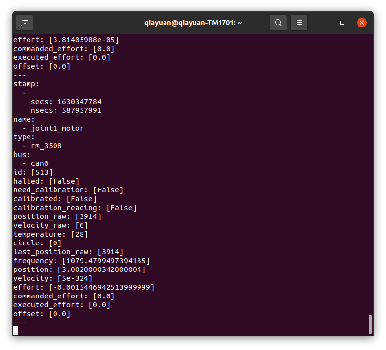
使用 rostopic 获取执行器(3508 电机)的状态,转动 3508 的转子观察数据。
rostopic echo /actuator_states
使用下述指令开启 joint_state_controller ,该控制器(其实是发布器)会吧关节状态发布出去。
rosservice call /controller_manager/switch_controller "start_controllers: ['controllers/joint_state_controller']
stop_controllers: ['']
strictness: 1
start_asap: true
timeout: 0.0"
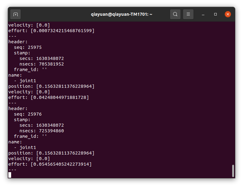
使用 rostopic 获取 joint1 的状态,转动 3508 的输出轴观察数据。
rostopic echo /joint_states
danger
接下来关节/执行器将会运动,如果你在尝试使用真实 3508 电机,请稳定固定好电机防止意外伤害。
位置控制器
停止运行速度控制器,运行位置控制器的指令如下:
rosservice call /controller_manager/switch_controller "start_controllers: ['controllers/joint1_position_controller']
stop_controllers: ['controllers/joint1_velocity_controller']
strictness: 1
start_asap: true
timeout: 0.0"
此时位置闭环已经开始进行,通过 rostopic 发送位置指令 0.0, 可以观察到仿真中 link2 快速移动到水平位置或真实电机移动到零点 。改变发送指令的数值观察现象。这时候可以很方便地将各个数据可视化
rostopic pub /controllers/joint1_position_controller/command std_msgs/Float64 "data: 0.0"
tip
在 ROS 中,所有数据的单位都是国际标准单位,如:角度为 rad,角速度为 rad/s。
速度控制器
停止运行位置控制器,运行速度控制器的指令如下:
rosservice call /controller_manager/switch_controller "start_controllers: ['controllers/joint1_velocity_controller']
stop_controllers: ['controllers/joint1_position_controller']
strictness: 1
start_asap: true
timeout: 0.0"
通过 rostopic 发送位置指令 3.1415, 可以观察到仿真中的 link2 或真实电机以半圈每秒的速度旋转。
rostopic pub /controllers/joint1_velocity_controller/command std_msgs/Float64 "data: 3.1415"
TODO 可视化
ROS 提供了非常多的可视化工具,你可以绘制电机各个数据的图像、查看各个坐标系的关系、动态调整 PID 参数。